Timeline
02/2020 - 05/2020 (3 months)
Team
Saisaran Kidambi, Daisy Lu, Jake Nuesca, Noah Raymond, Nicole Wang, Stanley Wang
Objectives
In this project (for the course E26: 3D Modeling for Design), we aim to maximize the tower stiffness of the wind turbine in a simulated acrylonitrile butadiene styrene (ABS) model. We need to determine the optimal wind turbine body and blade designs to make it strong and durable. Then, we need to complete the Finite Element Analysis (FEA) simulations to optimize our product. Overall, this project helps us understand the fundamentals of the design and creation processes, and gain experience with CAD modeling, real-life engineering applications & industry products.
I. Specifications
Some important differences between this model and an actual wind turbine include the materials used and the size. While this model uses a lightweight ABS plastic and is on the scale of inches, wind turbines used in practice are often made of steel or other metals and are typically hundreds of feet tall. This meant that our material was less strong, but that the tower had a lighter load to handle.
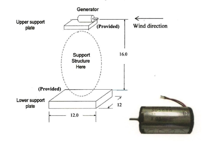
- The rotor hub was given; a Maxon A-max motor (26mm x 45mm) was provided to act as the generator
- A total tower volume no more than 18 in^3
- The tower was to have radial symmetry and three or more contact points with the floor or platform
- Stand on a 12”x 12” x 3/8” platform of solid ABS
- There may be fasteners or other supports for the tower on top of the platform, but not on the bottom
- The height from the motor shaft’s center to the top of the platform was to be within 1/16th inch of 16 inches.
- The motor needed to be supported by an upper platform
- There needed to be a 3/16” hole in the model, centered at the motor shaft, for the eyebolt
- The blades could be no longer than 3 inches, for a total diameter no larger than 6 inches
- All parts of the model were able to be fabricated from the 3-D printer
II. Blade Designs
While the material was fixed, the blades of the turbine could still be modified by number, length, profile, and pitch. We chose to explore the existing family of NACA airfoils, which are defined using either four or five-digit codes that specify properties of the airfoil shape such as camber and thickness. The geometry of the airfoil can be fully defined using a set of analytical equations, which describe the curve used as the geometric centerline of the airfoil shape, as well as the thickness distribution along this centerline (Marzocca 2016).
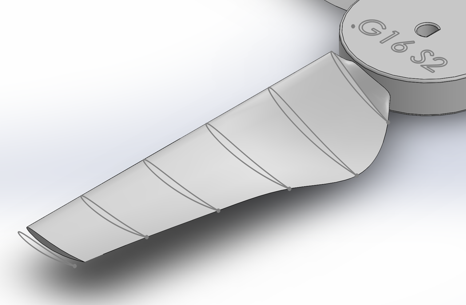
Location and Orientation of NACA 5510 Loft Profiles in SOLIDWORKS
Location and Orientation of NACA 5510 Loft Profiles in SOLIDWORKS
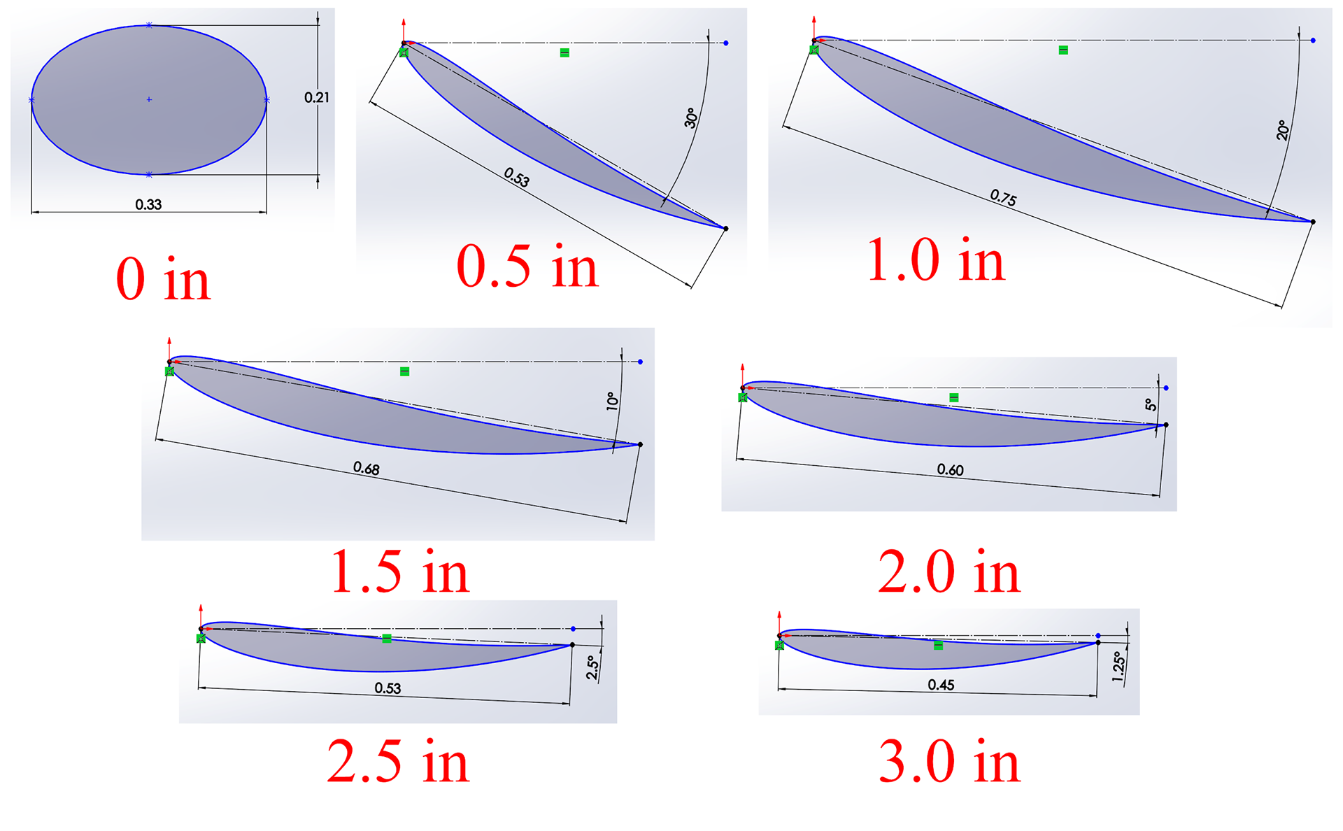
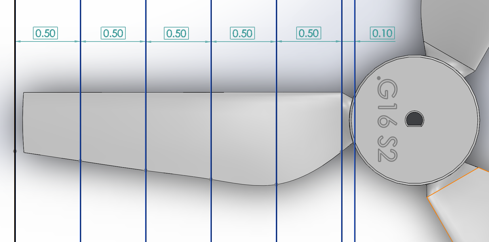
Dimensions of NACA 5510 Profiles Defined Along the Span of the Blade. The elliptical profile is used to help the blade smoothly intersect with the hub of the turbine.
Increasing the number of blades increases the theoretical energy yield from the turbine, but the gain from each additional blade tends to decrease. Also, since each blade adds more weight, requires more material, and increases the resistance, the best designs tend to have the minimum number of blades to generate torque and maintain balance, and with an odd number of blades to avoid balance issues. To create the complete part, the blade was simply duplicated in a circular pattern around the provided hub part to create a three-bladed turbine. Finally, to ensure the complete rotor swept a circular area not exceeding 6 inches in diameter, an extruded cut was used to trim away a small portion of the ends of each blade.
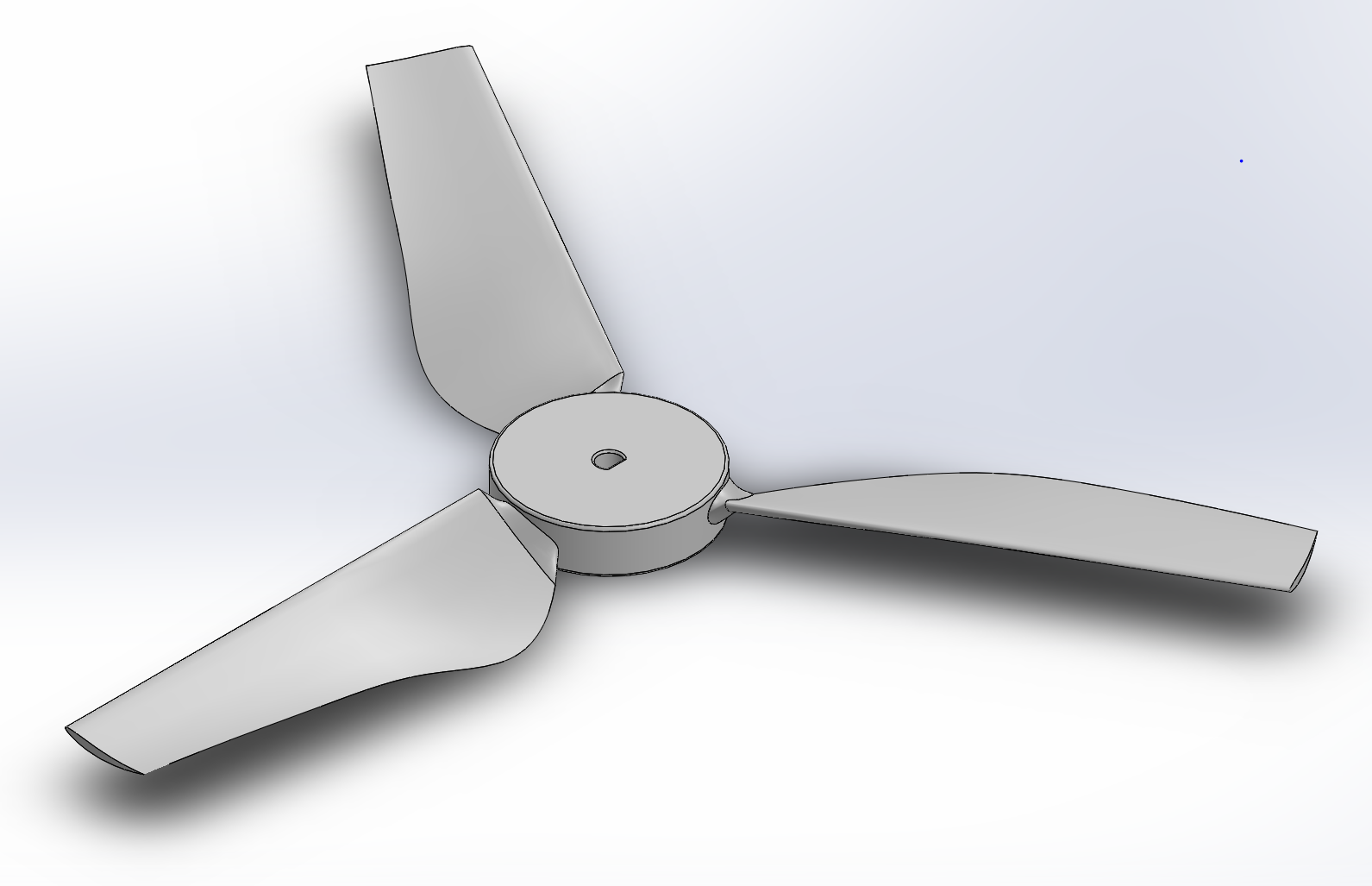
Isometric View of the Turbine Blade
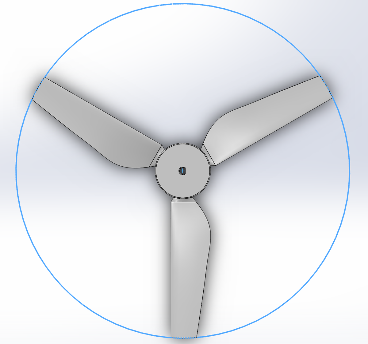
Top View of the Turbine Blade Constrained Within a 6 inch Diameter Circle
III. Tower Design
The wind turbine tower was an optimization problem – the goal was to maximize stiffness while minimizing weight. Stiffness is important so that the tower doesn’t move with the blades, and since this is dependent on the deflection of the tower, greater stiffness tends to come with a greater moment of inertia. By applying properties of inertia, the same stiffness can be achieved with a fraction of the material. Optimal design geometries were explored using the generative design tool in Fusion 360. Generative design is an iterative design process, where constraints in the form of design parameters and objectives are initially specified – followed by a series of successive outcomes generated by the computer software.
For the particular design of the tower, we chose to create a three-legged tripod-shaped structure in order to achieve the necessary radial symmetry specified for this project, while maintaining a relatively simple geometry to optimize. Our generative design study was performed using a simplified model of a single leg of the tripod. Physical constraints are subsequently applied after our starting geometries are defined. The generative study as previously described converged after 58 iterations, taking roughly two hours of computational time. The final outcome had a volume of approximately 5.8 in^3 , a minimum factor of safety of 46, and a maximum global displacement of 0.11 mm.
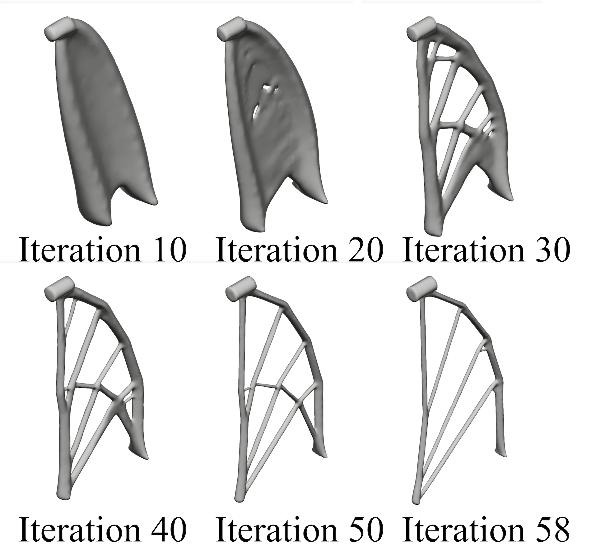
Evolution of Design Geometry through Successive Iterations of Generative Design
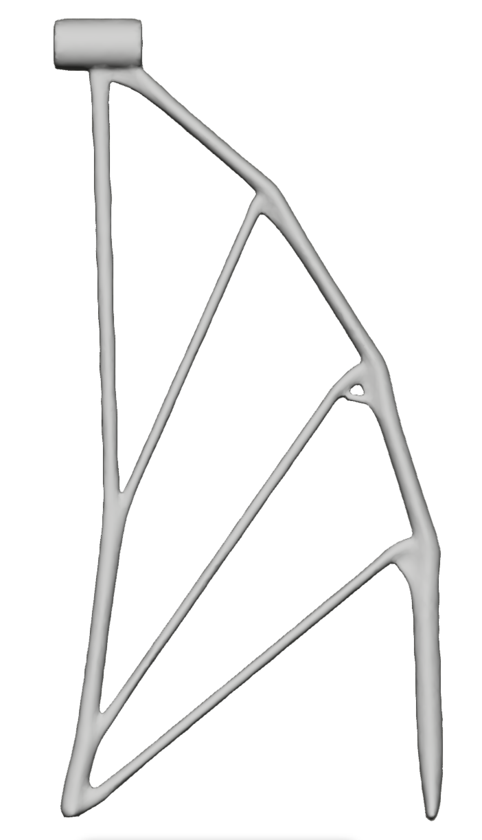
Side View of Final Generative Outcome
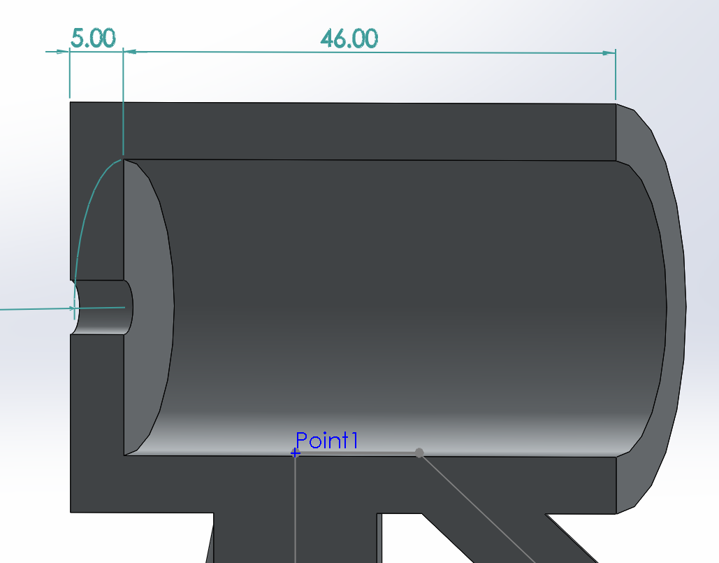
Dimensions of the Tower Motor Mount
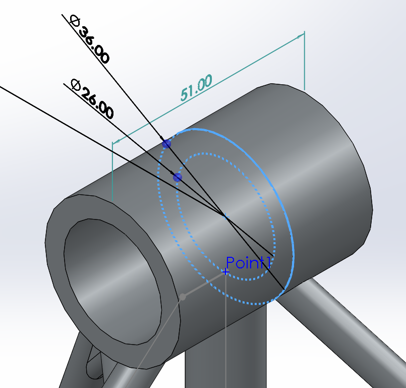
Dimensions of the Tower Motor Mount
After making use of Fusion 360’s generative design feature, we then imported the tower design into SOLIDWORKS, to add remaining design details and conduct finite element analysis.
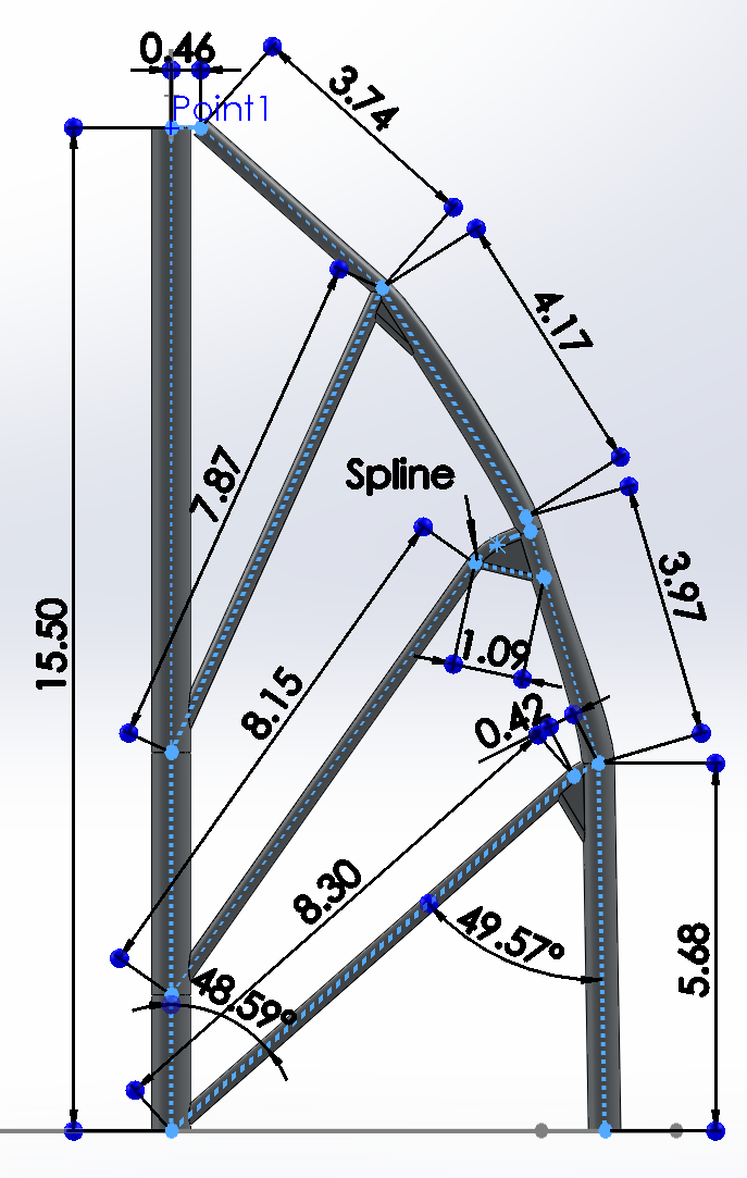
Approximate dimensions of one leg of the tripod, taken by tracing over the freeform generative design in SOLIDWORKS with sketch lines, followed by sweeps and extruded fins
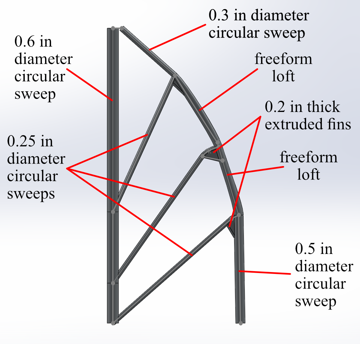
Description of SOLIDWORKS features used to create one leg of the tripod. The tower is formed using a circular pattern along the axis of the 0.6 in. swept vertical cylinder
IV. CAD Simulation
- External loading was applied to the backplate of the motor mount. A total of 20 simulations were run, in increments of 100 gf and starting at 100 gf (gram-force)
- Displacement measurements were taken in two ways: the built-in maximum displacement annotation and probing tool
- In the final simulation (2000 gf external load), further measurements of FOS (factor of safety) and stress were taken, in addition to the regular displacement measurements
- Measurements of most interest include minimum FOS, maximum stress, and displacement at the motor mount
- The central pillar bends the most, causing points along the pillar to have a higher deflection than the actual motor mount, so displacement measurements were also taken on the lower lip of the motor mount.
Results
- Displacement results were remarkably linear
- Stiffness calculations were also simplified to the linearity; stiffness at the motor mount was found to be 80.7 N/mm, and the stiffness of the central pillar was found to be 53.1 N/mm.
- Maximum stress occurs where the central pillar attaches to the ground; stresses are also higher in the leading support post
- The minimum FOS is also where the central pillar attaches to the ground - this area is where the tower is likely to fail at higher loads
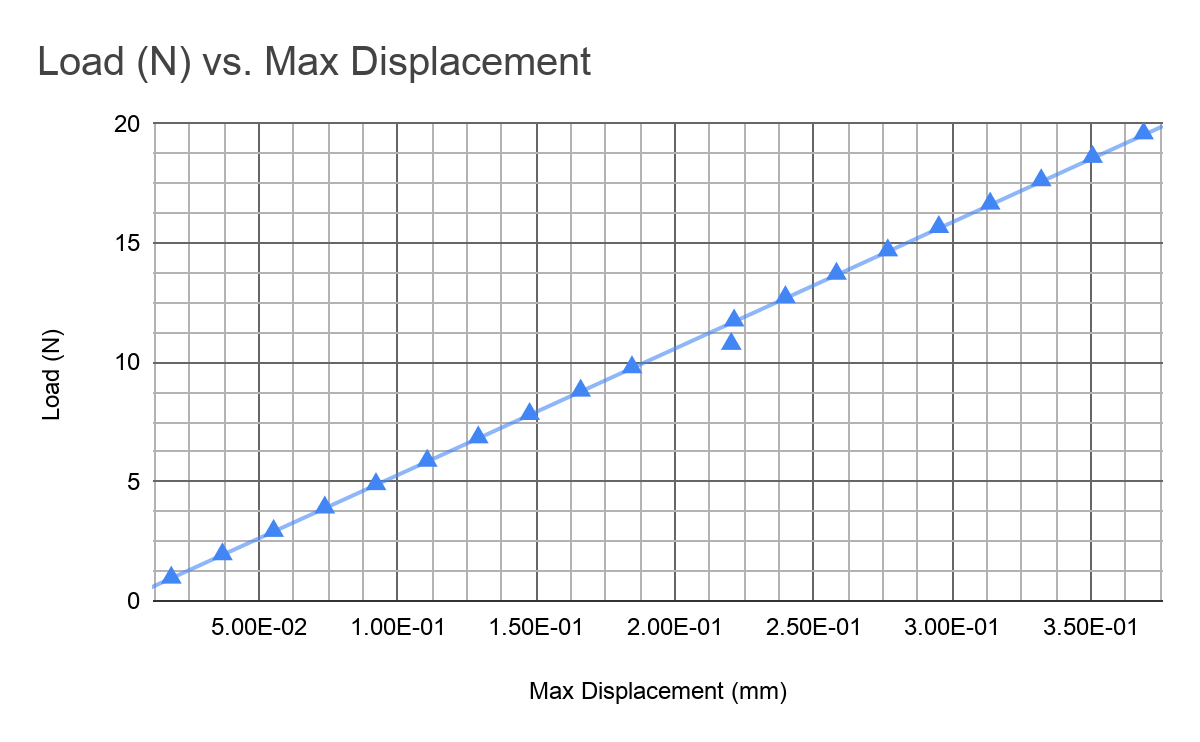
Load vs Displacement Chart; Maximum Displacement Along Central Pillar
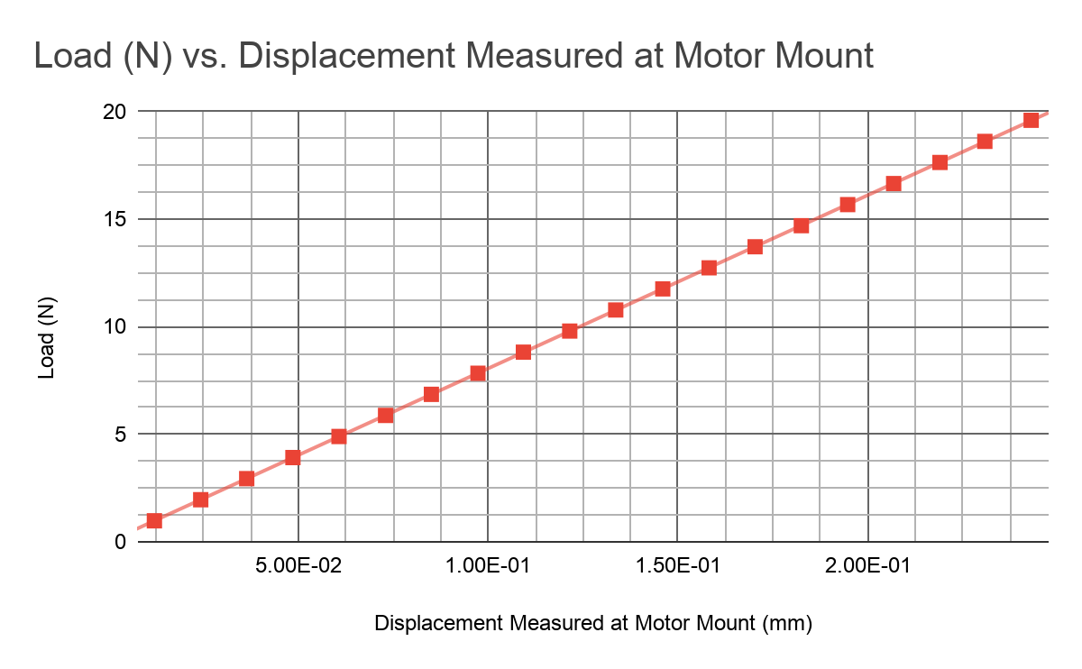
Load vs Displacement Chart; Displacement Measured at Motor Mount
V. Future Recommendations
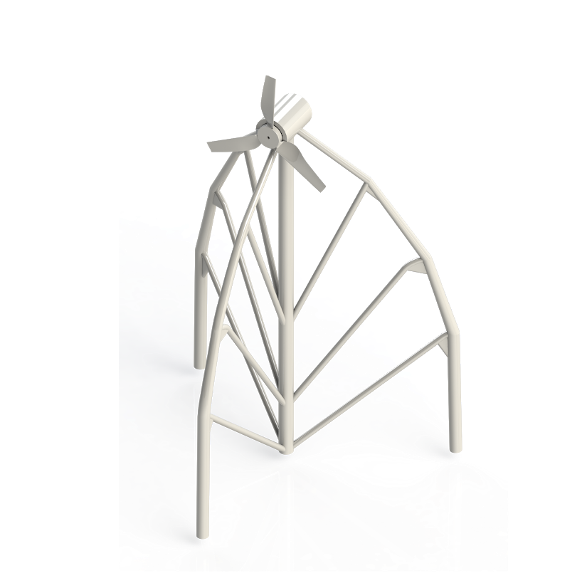
A complete, assembled model
Due to COVID-19 circumstances, instruction changed to remote during the middle of the semester, and we were not able to create a physical prototype. Therefore, a lot of important parameters were not tested. The digital model in SolidWorks, due to theoretical limitations, may poorly estimate the actual product behavior. So in order for us to obtain better results, one recommendation would be to build a physical prototype. This would allow us to better observe the behavior of the wind turbine, and to test the performance of the wind turbine through additional factors, such as the efficiency and the generated power.
Every team member also made an individual sketch of the tower concept, each has different schematics. If we had more time, we could model more tower concepts in SolidWorks and see which has the maximum stiffness or minimum weight. This would allow us to have more options to choose from and thus optimize our tower design. For example, lattice structure has made tremendous architectural achievements due to its high strength-to-weight ratio, high surface area, and other mechanical benefits. We could employ this structure in our tower design to see if it enhances the performance of the wind turbine.